


Description
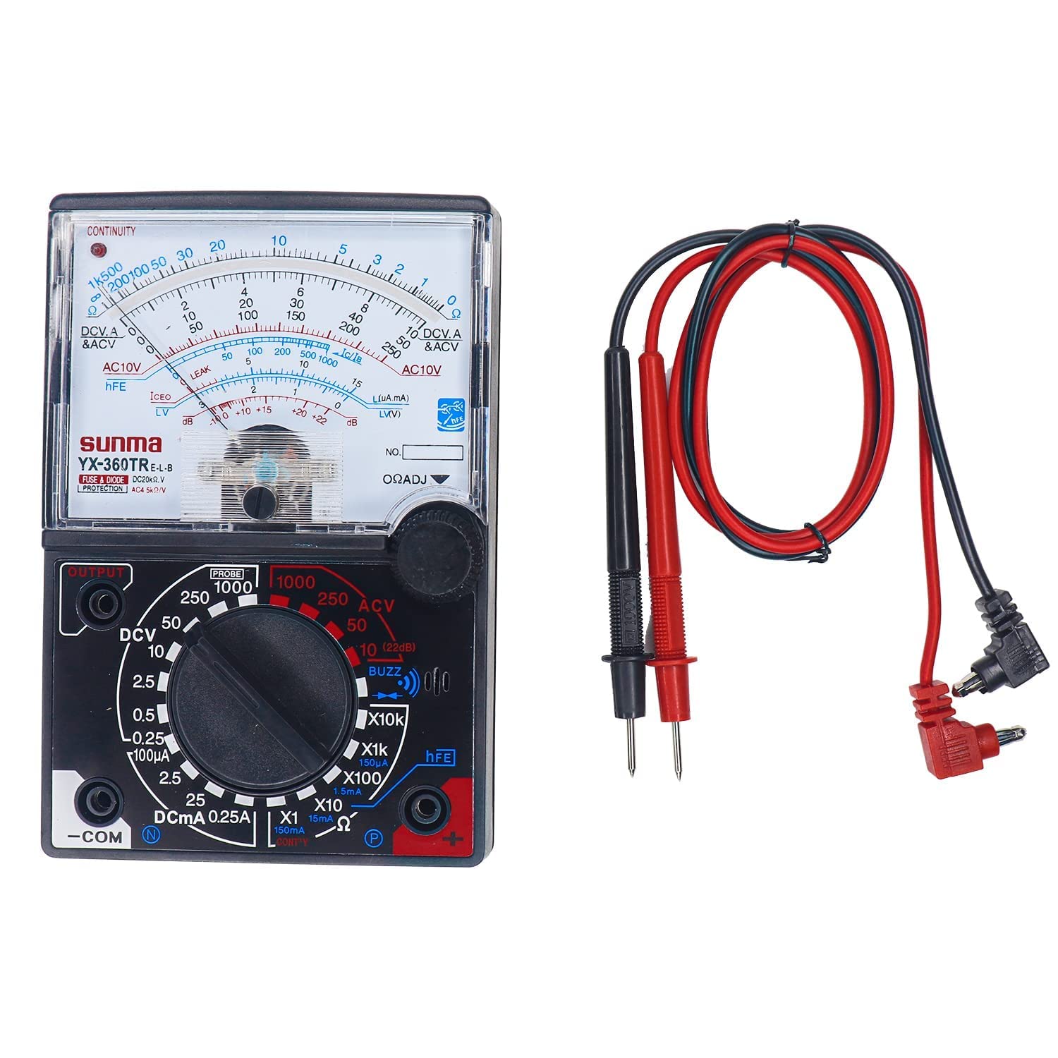
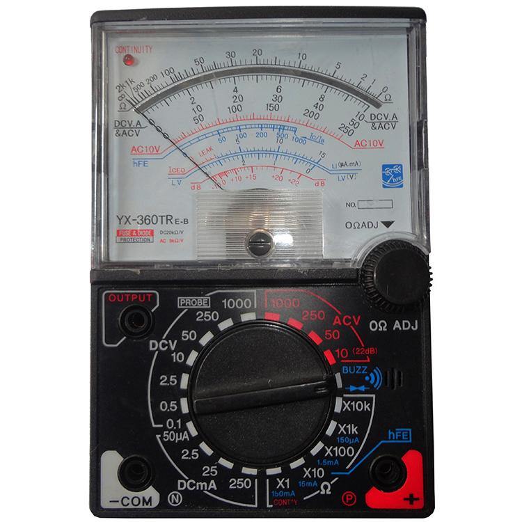
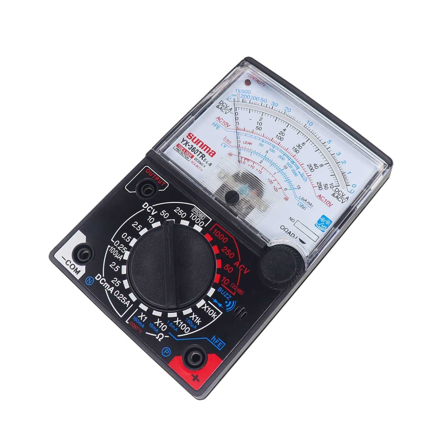
YX-360TR Analog Multimeter DC-20kohm.V/AC-5kohm/V for AC/DC Voltage & Current Analog Multimeter
SPECIFICATION
DC VOLTAGE
Ranges: 0.1-0.5-2.5-10-50-250-1000V
Accuracy at FSD: 3;(1000V;5)
Sensitivity :20k Q/V
Extension :25kV(with HV probe extra)
AC VOLTAGE:
Ranges: 10-50-250-1000V
Accuracy at FSD. 4;(1000V;5)
Sensitivity :9K Q/V
Decibel meter : -10 to + 22dB
OdB=1mw/6009
DC CURRENT
Ranges: 50 μA(at 0.1VDC position), 2.5mA, 25mA, 0.25A, * 10A
Accuracy at FSD: 3(10A;5)
Voltage Drop: 250mV
RESISTANCE:
Ranges:
x1-0.28Ω up to 2kΩ, Midseale, at 20Ω
x10-2Ω up to 20k, Midseale, at 20Ω
x100 x 100-20Ω up to 200 kΩ, Midseale, at 2kΩ
x1K-200Ω up to 2MΩ, Midseale, at 20KΩ
x I0 K-2KΩ up to 20MΩ, Midseale, at 200KΩ
Accuracy at FSD: 3
Iceo 150 μA- 15mA-150mA
hFE 0-1000 (with connector extra)
Size: 148 X100 X 35
Weight: 280g
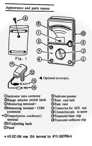
OPERATION:
ΩTEST
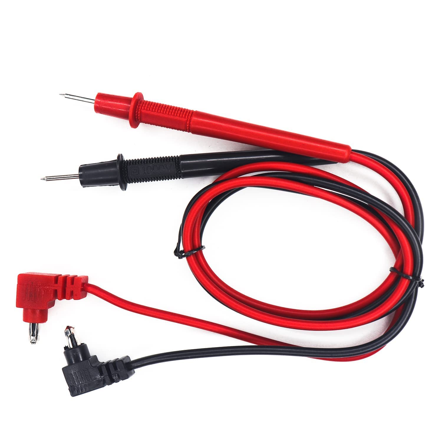
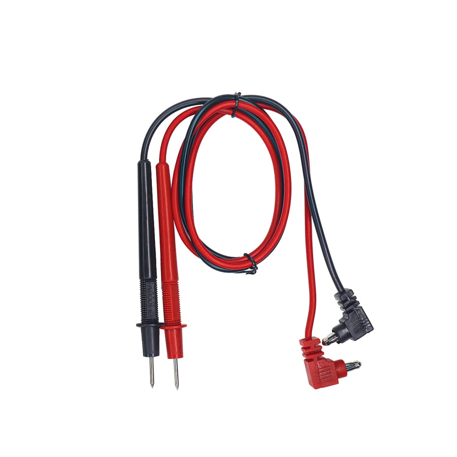
(1) Plug the test leads into COM and + sockets.
(2) Place the range selector in a prescribed range position.
(3) Short the test leads and turn 0 S ADS to set the pointer to zero position.
(4) Make sure that there is no voltage across the circuit to be tested.
(5) Connect the test leads to the tested resistor and read the scale in accordance with the reference table.
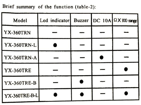
(6)* CONTINUITY TEST (BUZZ)
Set the range selector knob to BUZZ, apply the test lead pins to two points to be tested, and test continuity. Then the buzzer will buzz at between 0 and about 120Ω. It is impossible to test a point where voltage is being applied.
(7) ** CONTINUITY TEST (LED)
Set the range selector to the" CONT 'Y" position. Connect the test leads to the tested circuit. If the "LED" in the tester produces light, that means the tested circuit is continuous.
DCV TEST
(1) Plug the red test lead into the + socket and the black one into the COM.
(2) Set the range selector to a selected DCV range position.
(3) Connect the red test lead to the positive polarity of the circuit tested and the black one to the negative.
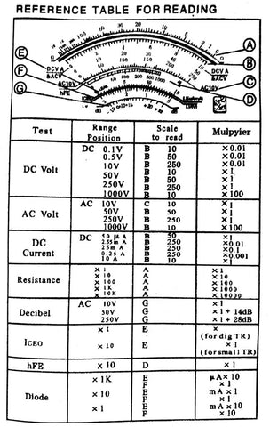
(4) Read the DCV A scale referring to the reference table.
ACV TEST
(1) Plug the red test leads into the +socket and the black into the -COM socket.
(2) Set the range selector to a chosen ACV range position.
(3) Connect the test leads to the circuit being tested regardless of the polarities.
(4) Read the AC scale with the reference 1e.
DCA TEST
(1) 50 μA-250mA
Place the red test lead into the + socket and the black into the COM.
(2) 10A
Place the red test lead into the DC 10A MAX socket and the black into the - COM.
Set the range selector at a selected DCA range position.
Connect the red test lead to the positive polarity of the circuit tested and the black to the negative.
Read the DC A scale converted with the reference table.
ACV TEST ON OUTPUT TERMINAL
Plug the red test lead into the OUTPUT socket and the black one into the COM.
Set the range selector at the selected range position.
Connect the test leads to the circuit to be tested and read the scale in the same manner as the ACV test. Such a measurement is made to block the DC voltage which present In the same circuit and must be cut out so that AC voltage can be read alone.
TRANSISTOR TEST
1. Iceo (leakage current) test.
1) Plug the test leads into + and - COM sockets.
2) Set the range selector to X10(15mA) for smallsize transistor,or to X1 (150mA) for big size transistor.
3) Adjust 0S addition to set the pointer to the zero position of the scale.
4) Connect the transistor with the tester:
For the NPN transistor, the N-terminal of the tester is connected with the COLLECTOR(C) of the transistor and the P-terminal with the EMITTER(E) of the transistor.
For the PNP transistor, reverse the NPN transistor connection
5) Read Iceo range, If the pointer is not within the LEAK zone or the pointer moves up near to the full scale, the transistor tested is not good, Otherwise, it ts a good transistor.
2. hFE (DC amplification) test
(1) Set the range selector to X10.
(2) Adjust 0 ADJ to adjust the pointer to zero position.
(3) Connect the transistor to the tester:
For the NPN transistor, A) connect the 'P' terminal of the tester to the emitter of the transistor with the hE test lead. B) Plug the hFE connector into the 'N' terminal and connect its red clip to the collector and the black one to the base of the transistor.
For the PNP transistor. A) connect the 'N'terminal of the tester to the emitter of the transistor. B) plug the hFE connector into the 'P' terminal and connect the clips in the same way as for the NPN transistor connection.
(4) Read the hFE scale. The value of the reading is Ic/Ib. which is the DC amplification degree of the transistor tested.
3. DIODE TEST
(1) Set the range selector at the selected range position - X1K for 0- 150M A, XIO for 0 - 15mA, XI for 0-150mA test.
(2) Connect the diode to the tester
For the If (forward current) test connect the "N" terminal of the tester to the positive polarity of the diode and the "p" terminal to the negative polarity of the diode.
For the I (reverse current) test, reverse the connection.
(3) Read IF or Ir on the LI scale provided.
(4) Read the linear (forward) voltage of the diode on the
LV scale while testing IF or Ir.