


Description
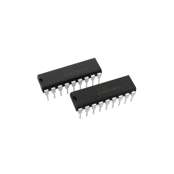
HT12E / HT12D Encoder–Decoder DIP IC for RF & IR Wireless Communication
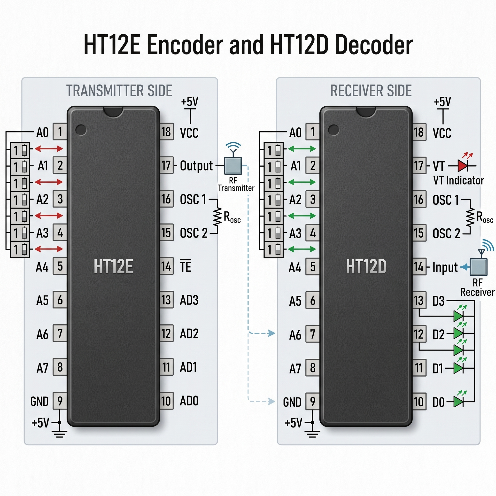
The HT12 series ICs consist of HT12E (Encoder) and HT12D (Decoder), widely used for wireless communication systems using RF (433MHz) or IR modules. These ICs convert parallel data into serial transmission and then decode it back, enabling simple remote control and automation systems.
The HT12E encoder takes input from switches or microcontrollers and converts it into serial data, while the HT12D decoder receives this data via RF/IR receiver modules and converts it back to parallel output. Together, they form a complete wireless data transmission system.
They are commonly used in remote controls, wireless switches, home automation, and robotics projects, making them essential components for beginners and professionals alike.
Key Features
- 12-bit encoding/decoding (8 address + 4 data bits)
- Supports RF and IR wireless communication
- Wide operating voltage: 2.4V – 12V
- Low power consumption (CMOS technology)
- Built-in oscillator (requires external resistor)
- High noise immunity and reliable transmission
Applications
- RF remote control systems
- Wireless switches and relays
- Home automation projects
- Robotics control systems
- Security and alarm systems
- DIY electronics learning