Introduction
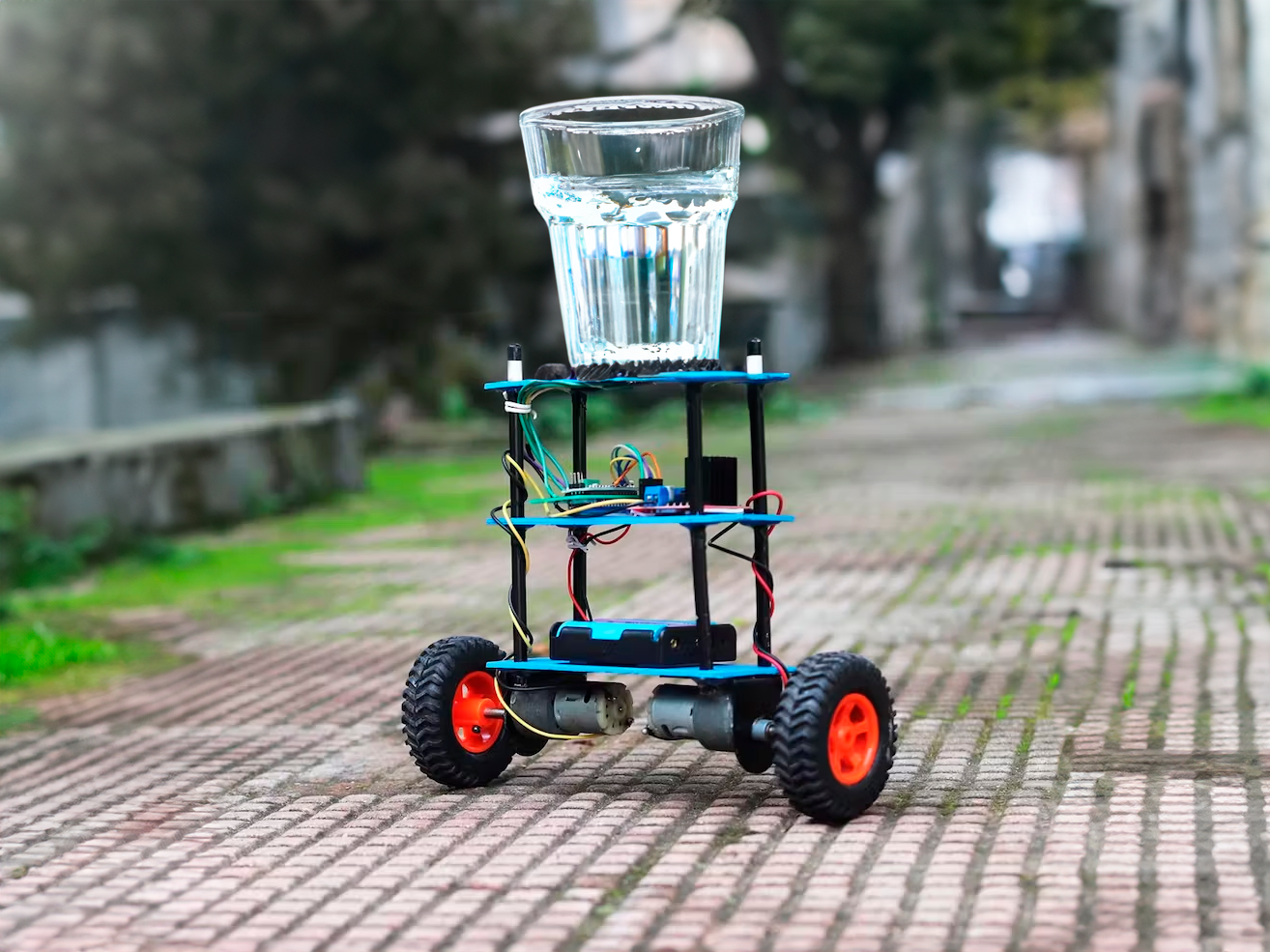
In the world of robotics and automation, self-balancing robots have always been an intriguing and impressive innovation. These robots have the capability to maintain their balance and stability without any external support. One of the key components that enable this remarkable functionality is the gyro sensor. In this blog, we will explore how to build a DIY self-balancing robot using a gyro sensor, providing step-by-step instructions and insights into the fascinating world of robotics.
Materials Required
To get started with building your own DIY self-balancing robot, you will need the following materials:
- Arduino Uno board
- MPU6050 accelerometer and gyroscope Sensor
- Motor driver (L298N or L293D)
- Two DC motors with wheels
- Chassis or frame to hold the components
- 9V battery and battery holder
- Jumper wires and Breadboard
- 9V Battery and Battery Connector
- Smartphone or Bluetooth Module (optional, for remote control)
Understanding the Components
- Arduino Uno: The Arduino Uno is a widely used microcontroller board that serves as the brain of our robot. It can read inputs from various sensors, make decisions based on programmed instructions, and control motors and actuators.
- MPU6050: This module contains an accelerometer and gyroscope, which are essential for measuring the robot's orientation and detecting tilting and acceleration. These readings are crucial for the self-balancing functionality.
- Motor Driver: A motor driver is necessary to control the two DC motors used for movement. It takes the low-power signals from the Arduino and amplifies them to drive the motors effectively.
- DC Motors with Wheels: DC motors are responsible for propelling the robot. The wheels attached to the motors allow it to move in any direction.
- Chassis: The chassis is the body of the robot, which holds all the components together. It can be made from materials like acrylic, aluminum, or even 3D-printed plastic.
Building the Self-Balancing Robot
Step 1: Assemble the Chassis Begin by assembling the chassis or frame of your robot. You can either use a pre-made chassis kit or build one from scratch using materials like acrylic or wood. Ensure that the motors fit securely in place and that there is enough space to accommodate the other components.
Step 2: Connect the Motors Attach the two geared DC motors to the chassis—one on the left side and the other on the right side. Connect the motors to the motor driver module (L298N) using appropriate wires. The motor driver will act as an interface between the motors and the Arduino, allowing you to control the robot's movement.
Step 3: Install the Gyro Sensor Mount the gyro sensor module (MPU6050) on the chassis. It is best to position it at the center of the robot, between the two wheels. The sensor will be responsible for detecting the robot's tilt and providing feedback to the Arduino.
Step 4: Connect the Gyro Sensor Connect the gyro sensor to the Arduino board using jumper wires. Typically, the MPU6050 has four pins: VCC, GND, SDA, and SCL. Connect VCC and GND to the corresponding pins on the Arduino for power supply, and SDA and SCL to the I2C pins (A4 and A5) for communication.
Step 5: Program the Arduino Now comes the coding part. Write the Arduino program that reads the sensor data from the gyro sensor and controls the motors based on the tilt angle to maintain balance. You can use the Arduino IDE (Integrated Development Environment) for writing and uploading the code to the Arduino board.
To keep the code within the word limit of this blog, we'll provide a basic outline of the process:
// Include necessary libraries
#include <Wire.h>
#include <MPU6050.h>
// Initialize MPU6050
MPU6050 mpu;
// Define motor control pins
int motorPin1 = 10;
int motorPin2 = 11;
// Repeat the above two lines for the second motor
// Define variables for angle and motor control
float angle;
float setpoint = 0; // Desired tilt angle (adjust as needed)
float Kp = 2.5; // Proportional gain (adjust as needed)
void setup() {
// Initialize serial communication for debugging
Serial.begin(9600);
// Initialize MPU6050
mpu.initialize();
// Attach motor control pins
pinMode(motorPin1, OUTPUT);
pinMode(motorPin2, OUTPUT);
// Repeat the above two lines for the second motor
}
void loop() {
// Read raw sensor data
int16_t gyroX = mpu.getRotationX();
int16_t gyroY = mpu.getRotationY();
// Calculate the tilt angle using gyro data
angle = atan2(-gyroY, gyroX) * 180 / PI;
// Compute the motor control signal using the PID controller
float error = setpoint - angle;
int motorSpeed = Kp * error;
// Apply motor control signals to keep the robot balanced
// Use motorSpeed to control both motors appropriately (e.g., one forward, one backward)
// Adjust motorSpeed to maintain balance
// Print angle and motorSpeed for debugging
Serial.print("Angle: ");
Serial.print(angle);
Serial.print(" Motor Speed: ");
Serial.println(motorSpeed);
}
Step 6: Power Up the Robot Connect a 9V battery to the Arduino and the motor driver module. Ensure that the connections are secure and the power supply is stable.
Step 7: Test and Fine-Tune Turn on the robot and observe its behavior. If everything is set up correctly, the robot should attempt to balance itself on its wheels. However, achieving perfect balance might require some fine-tuning of the code. Adjust the PID controller parameters and the setpoint as needed to enhance the robot's stability.
Optional: Remote Control If you want to add more functionality to your self-balancing robot, you can incorporate a smartphone or Bluetooth module. This will allow you to control the robot remotely, making it move in different directions or perform specific tasks.
Conclusion
Building a DIY self-balancing robot using a gyro sensor is a rewarding and educational experience. It provides valuable insights into robotics, sensor integration, and control systems. As you experiment and improve upon the basic design, you'll discover endless possibilities for customization and enhancement. So, unleash your creativity and embark on this exciting journey into the world of self-balancing robots! Happy tinkering!

